Week of Feb.4 th
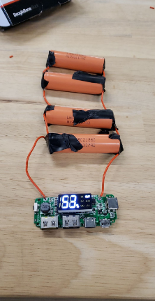
In this week the goal was to make and estimation of the runtime of the device through batteries. So, I connected the chip which is in our case was the beagle bone, and using the USB tester I note the reading of the amps and the voltage that is being dropped. The power supply that I used was the 18650 charger with 4x 18650 batteries.
This power supply have roughly 10124 mAh. To get the estimated hours that the chip can run before the battery need to be charged again I used the following rules.
Battery Life = Battery Capacity in mAh / Load Current in mA * 0.70
Runtime = (10 * Ampere Hours) / Load in Watts
I am still doing more research on batteries to see what will fit our project but for now I can say that I achieved a runtime between 5-10 hrs using those batteries.
Parts used:
USB TESTER: https://www.amazon.com/DROK-Multimeter-Multifunctional-Electrical-Capacity/dp/B00J3JSEG6/ref=pd_lpo_vtph_60_tr_t_2?_encoding=UTF8&psc=1&refRID=9950SMJQZR41SE4KKYR2
18650 Batteries: https://www.imrbatteries.com/hohm-work-18650-2531mah-flat-top-battery/
Week of Feb. 11
Since we are getting another chip for implementing our project I am going to extended my testing for power consumption as I am trying to get an accurate estimation in order to have the right battery to supply the right amount of voltage.
In addition, I am going to start practising to design a 3D model to be printed so i can fit all the parts in it. This will be established once I get the battery. In the meantime i am still learning and practising on how to design it.
Week of Feb. 18
So I finish estimating the power consumption of our device and we decided to reuse old laptop batteries in our power supply. Next, since we might face heat issues we decided to have extra fan comes to total of two fans . Then we worked on connecting the fans to the beaglebone. Right now we are working in designing the case as well as put everything in terms of hardware together.
Week of Feb.25
Redesign battery with 12V output rather than 5V output so it can work with the Udoo board. Also working on powering the device using just the car cigarette lighter. Taking measurements of all the power outputs in car.
Week of Mar. 4
The PCB that we are using in the new battery doesn’t work as it should as it keep charging the batteries even when the batteries are fully charged so we ordered a new one. So far the battery is ready but we are still working on connecting it to each component to supply power.
Week of Mar.18
We are working on finalizing the output power to make sure it meets the 12 V that will be required by the UDOO Board. We encounter some issues with the battery voltage reading and for now we are assuming it is because we have different battery brands with different capacity.
https://batteryuniversity.com/learn/archive/is_lithium_ion_the_ideal_battery
https://www.apartmenttherapy.com/tech-legend-is-it-safe-to-mix-153264
Week of Mar 25
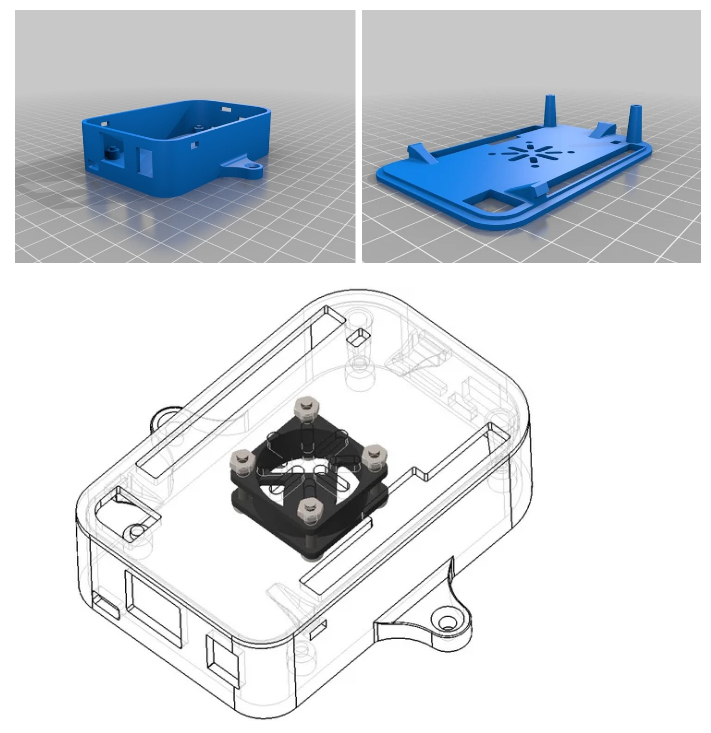
Finished the power supply. Working on connect thermometer and accelerometer to the new chip we are getting since the beaglebone got broken. I am going to use the 3d printing for the beaglebone case for the final product.

https://www.thingiverse.com/thing:1921059
Also we started connecting the screen to the raspberry pie and we finished it. We used the following links as a reference for the pins that will be connected. We still didn’t test it as we need our software team to write a code for it.
https://www.waveshare.com/w/upload/2/20/4.2inch-e-paper-module-user-manual-en.pdf
https://www.waveshare.com/w/upload/6/6a/4.2inch-e-paper-specification.pdf
Week of April 1
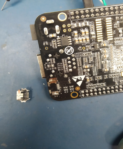
So since our beaglebone power input got broken we worked on fixing it but we failed.

The good news is that we can still power it using 5v input build in. Next, we had to change the power supply which we already build since we are not using the UDOO board which used to require 12V. So we are sticking to the same amount of batteries and we are going to change the chip to supply 5V for the new board we got the raspberry pi 3. We finished printing the case for using 3d printer for beaglebone. Now we are working on case for the raspberry pie as well as a final case for everything. We want to make sure that the we have fan mounts.
Week of April 8
In this week we had tested the old laptop batteries first on the new PCB board.
First Attempt:
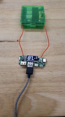
We encountered multiple issues working on that. First we had to solder normal wires to the batteries as the spot welder is not available in EEB which is not recommended. Next, we were not getting accurate reading as we found out that the batteries was not charged. We were not certain about that as we found one of the PCB boards are not working. So we build another power supply on the side to confirm that.
Second Attempt:
Next, we try using our power supply to power the beaglebone and it worked successfully.
I did a final test of discharging and charging the batteries to make sure they are working as they should.
Next step I will use 3d printer to make the battery holders. I will print two cases of the one bellow for testing purposes and incase if one failed for any reason.
Battery Case Holder:
https://www.thingiverse.com/thing:2862293
So the reason why I chose this design for my battery holder is because the spot welder (Fig.1) machine that I can use in to wire all batteries is not available in EEB Lab. So the other option is to use normal wires and solder. The problem with that is I am risking venting the batteries due to high temperature and it might lose the connection after sometime which is not something we want to happen. So the battery holder that i am using have screws and nuts that will do the job of the contact of both positive and negative (Fig.2). Then i used a copper wire that is coated to connect all terminals. Now the only thing is left is to try to find a way to isolate both bottom and top part to prevent any short circuit to happen. The idea that I have in mind right now is to use certain type of clay to mount it on it.
(Fig.1)
https://i.ebayimg.com/images/g/q~UAAOSw4A5YwlL3/s-l300.jpg
(Fig.2)
Week of April 22
In this week I worked on insulating both the top and bottom terminals for the battery holder using hot glue. Then I added two blocks of wood to make a gap between the batteries and the board to protect the board from any heat.
We decided to use led lights to be hooked all over the screen to have a better view in the night. We decided to add potentiometer which will allow the user to adjust how bright the light will be.

