Autofocus
A smart dashcam bringing modern computer-aided vision technology to automobiles everywhere.
Abstract
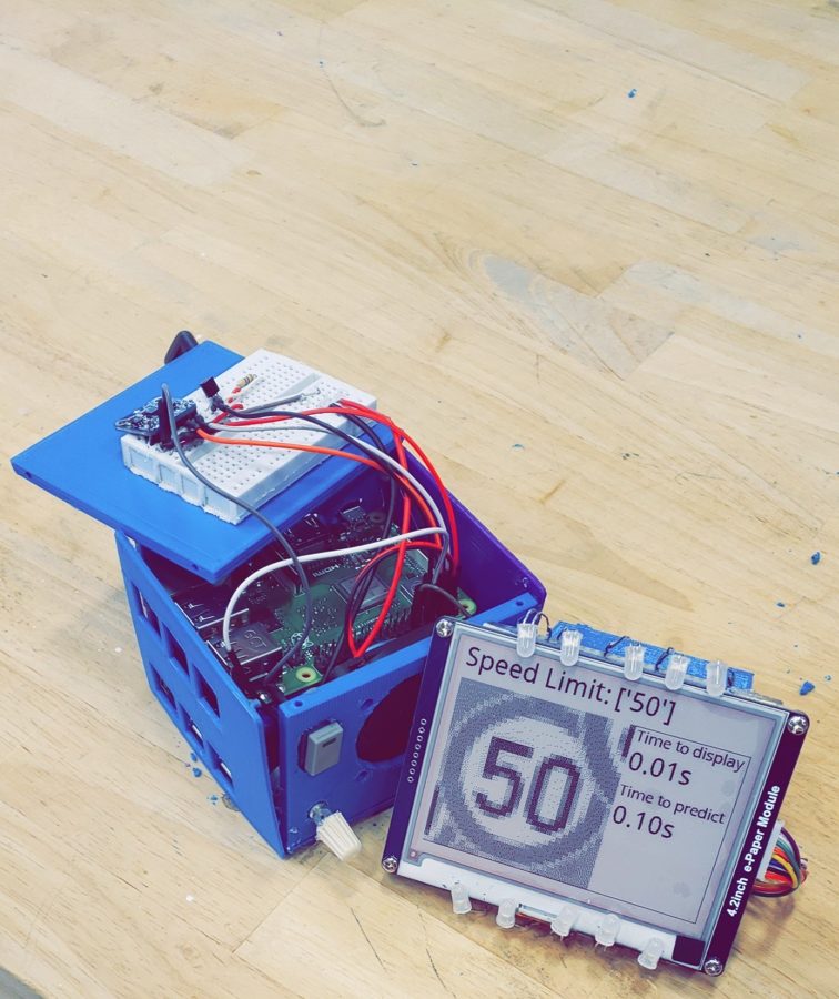
This device acts as a smart dashcam for motor vehicles. In addition to providing normal dashcam recording functionality, it uses modern machine learning techniques to analyze what is on the road and inform the driver. In this iteration of the device, it is specifically looking for speed limit signs. The device will take pictures while the user is driving and run these images through a preprocessor, which will find and crop out anything it detects as a speed limit sign. After more processing on the image is performed, such as color correction and threshold testing, it is sent to the neural network model for prediction. This is accomplished using two different Raspberry Pi 3bs, one which handles the taking and preprocessing of images, it then hands this to the second Pi which does the threshold testing and prediction. The resulting prediction is then displayed on an e-ink screen included with the device, as well as sent to a mobile app if it is connected. It is capable of predicting in under one tenth of a second allowing for, in the best case, almost real-time capture and prediction.
Introduction
As machine learning techniques continue to improve and expand, especially with respect to image processing, completely new applications present themselves. This project utilizes leading image prediction algorithms to assist automobile drivers on the road. By processing images captured using a mounted dash camera this system will detect road signs and report information back to the driver via a mounted screen and/or a smartphone application. The system is able to keep the driver informed of the current speed limit, construction zones, and any number of other potentially missed signage the driver passes by. The motivation behind this project was the thought that neither GPS’s or dashcams have had any sort of major innovation in the last decade, and in the era of smart devices there was surely more that they could be doing. This project provides users with a second pair of eyes while on the road to facilitate safer and more aware drivers, particularly drivers of vehicles without more modern technological aid features. This product is built with two raspberry pi’s that communicate using . On one board, a camera is connected that takes pictures at a rate of 30 per second, and the pictures are then processed down so that only the relevant signs are kept. These cropped signs are then saved as images, and sent through a processed which over saturates all colors. This oversaturation of colors allows for the program to use a color threshold, and separate the colored/black text of a sign from the white background. This process outputs a matrix of binary values which are sent over the the second board. In the second board, a machine learning algorithm made with SVM reads the matrix, and predicts what value or text is held in the sign that the matrix represents. That text is then shared with a phone app that can be used in a number of different ways, and is also sent to an e-ink display to keep the driver informed of what it just read. The entire process described above is done in under one tenth of a second, and with very minimal power draw. We believe that this is an acceptable amount of time for this process, and that the output along with the gathered information are highly valuable to the driver and to many different possible software applications.
AutoFocus device has many constraints both in terms of hardware and software.
Hardware constraints
Per “49 CFR 571.101 - Standard No. 101; Controls and displays”, the device should be located in within the reach of the driver, so it can be easily operated and seen within restrictions of seatbelt. [17]
The device has to be small enough to be mounted near the car dashboard, so it doesn’t distract the driver and impair his ability to safely navigate on the road . Since we are using two raspberry Pi devices, our size is constrained by these two microcontrollers since the case we designed has to fit both of these devices. Per § 571.302 Standard No. 302; Flammability of interior materials, all devices and parts inside a car need to be made of materials with low flammability. [16]
The device needs a constant 5V, 2.5 A power source, and since our initial target market consists of older car models which might not have an auxiliary power supply inside the car, so our only solution in this case is using a battery as a power source. In order to support the device for at least 4 to 5 hours the battery has to have a capacity of at least 10,000 mAh.
Also, the device will be exposed to a automobile environments where temperatures can be extreme. This puts constraints on all the electronics used and a battery. The Raspberry Pi 3 is built from commercial chips which are qualified to different temperature ranges; the LAN9514 (LAN9512 on older models with 2 USB ports) is specified by the manufacturers as being qualified from 0°C to 70°C, while the SoC is qualified from -40°C to 85°C [18]. Beyond these temperature ranges this microcontroller is not guaranteed to operate properly. Also, operating range of a battery is between -40°C and +70°C. High temperatures can greatly affect battery life. As a guideline, each 8°C (15°F) rise in temperature cuts the life of a sealed lead acid battery in half. This means that a VRLA battery for stationary applications specified to last for 10 years at 25°C (77°F) would only live 5 years if continuously exposed to 33°C (92°F) and 30 months if kept at a constant desert temperature of 41°C (106°F). Once the battery is damaged by heat, the capacity cannot be restored [18]. For these reasons, the device requires heat sinks for the microcontrollers and a fan installed inside the case to keep the air moving and cool the device down.
In addition, display screen size needs to be big enough to clearly display the image of the last speed limit sign the car passes. Also, per S5.3.2.2 article of the “49 CFR 571.101 - Standard No. 101; Controls and displays”, (a) the screen must be adjustable to provide at least two levels of brightness; (b) At a level of brightness other than the highest level, the identification of controls and indicators must be barely discernible to the driver who has adapted to dark ambient roadway condition; (c) May be operable manually or automatically; and (d) May have levels of brightness, other than the two required visible levels of brightness, at which those items and identification are not visible.[17] The screen also has a specified operational temperature between 0°C to 50°C. The screen is the biggest constraint in terms of temperature since it doesn’t perform well in cold temperatures.
In order to have a high quality pictures while driving we need to have a camera which takes pictures of at least 60 frames per second.
Lastly, the device and mobile phone interfacing with it both need to support Bluetooth Low Energy. Bluetooth LE was introduced in the Bluetooth 4.0 specification as an alternative to Bluetooth Classic. It is a power-conserving variant of its predecessor and is famous for its low cost, long battery life and ease of deployment. This is ideal for our device given that it runs on a battery. Additionally, the mobile phone needs to run an iOS5+ (iOS7+ preferred) or Android 4.3+ operating system and should stay within a range of under 100m to connect or sustain a connection.
Software constraints
The main software constraint for this project was that prediction times needed to be very fast, with an initial goal of under 5 seconds. Any slower than this and the device’s reliability in a real-world driving situation would become questionable. This put major constraints on what sort of algorithms were suitable. It also required optimizations to any stage of the process to which that would be applicable.
Design Approach
Our initial approach in terms of hardware design considered using udoo NEO board, and a BeagleBone Black board. Theoretically, those two boards would be powerful enough to handle the robust software requirements for our product. However, due to budget constraints and a goal of minimalistic project design, we decided to replace the udoo board with a Raspberry Pi 3b + for pre-processing. Additionally, the BeagleBone Black board’s micro USB port broke off, and we weren’t able to boot into it and program it. So, we decided to replace the BeagleBoneBlack with a Raspberry Pi 3b for prediction purposes and screen display. Raspberry Pi microcontrollers proved to actually be a better choice, since they can withstand harsher temperatures than Udoo and BeagleBone Black boards.
For image displaying purposes we choose 4.2 inch Waveshare e-paper module because it doesn’t consume any power when it is idle. A disadvantage of this module is that it doesn't have built in LED lights so some users might have problems seeing the display in dark. To overcome this problem, we installed LED lights around it. We had to comply to the Controls and Display standards of National Highway Traffic Safety Administration (NHSTA) and install a potentiometer to enable multiple levels of brightness of the screen.
In an effort to keep device as small as possible we designed a case for it. The case fits both microcontrollers, fan, and the additional sensors used. Due to our limited budget we decided to reuse old laptop batteries to build a portable power supply for our device, but we weren’t able to implement the battery inside the case, since it was too big for the case. This device requires a battery’s physical size to be close to the physical size of the microcontrollers used so it can fit the case properly and keep the device’s size minimal.
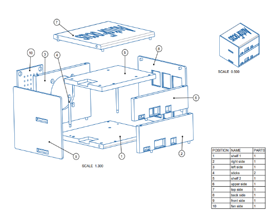
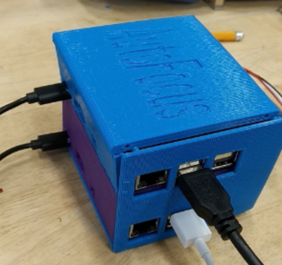
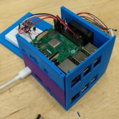
To satisfy NHSTA standard 303, the case needs to be built from material which doesn’t catch on fire easily. So, to satisfy this requirement AutoFocus device’s case should be built from 3 layers of materials: bottom layer which is a glass-fiber reinforced thermoplastic, middle layer of polyurethane foam, and top layer of PVC blended with a block copolymer made of acrylonitrile, butadiene, and styrene.
To provide enough power for the initial prototype we built a 5V, 2.5 A battery reusing batteries from an old laptop. We used 4 18650 lithium ion batteries connected in parallel to increase the overall capacity of the whole system. We used a voltage booster to step up the voltage so our device can have enough power all the time. In theory, this system should have a capacity of 10,000 mAh and last about 5 hours.
To keep the case cool we installed a 5V, 0.18A fan, and heat sinks to the microcontrollers. The fan is installed on the wall of the case, blowing air from one side to the other, so in this way its air flow can benefit both microcontrollers. To minimize power consumption the fan stays idle until the temperature of the device reaches 35 degrees celsius and at this point it starts cooling the system.
AutoFocus device uses a camera which takes pictures at 60 frames per second. The camera is also programmed in a way that it can save a video once the user presses a designated button on the case.